Electronics Design, Manufacturing & Electrification
PCB design, low-to-mid volume manufacturing, embedded hardware and full industrial-electrification projects — engineered in Lagos for industrial, commercial and residential clients across Nigeria.
20+ years · 500+ projects · Lagos-based engineering
From a sketch to a certified, shipped board — under one roof.
What We Deliver
Six tightly-scoped electronics services that take a product from a sketch on the back of a napkin to a certified, shipped board.
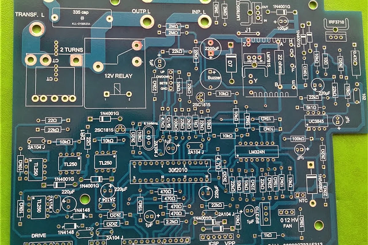
PCB Design & Prototyping
Schematic capture (KiCad / Altium), 2-to-8 layer PCB layout, signal-integrity review, and rapid prototyping. Working boards typically in 2–4 weeks.
Circuit Board Manufacturing
Small-to-medium batch PCB manufacturing with SMT and through-hole assembly. AOI inspection, X-ray for BGAs, and full pre-shipment functional test.
Embedded Electronics
Microcontroller-based product design on STM32, PIC, ESP32 and ARM Cortex platforms. Firmware and hardware co-designed under one roof.
Component Sourcing
OEM-grade parts via verified supply chains. We avoid the counterfeit risk that has bitten too many Lagos engineering teams.
Testing & SON Support
Functional, environmental and EMC pre-compliance testing, plus documentation support for SON certification when your product is destined for the Nigerian market.
Industrial Electrification
Industrial, commercial and residential electrification: single- and three-phase power distribution, panel design around Schneider, ABB and Siemens components, and full installation by COREN-aligned engineers.
Who We Serve
Teams we work well with — if you see yourself here, our process maps onto your needs without a long ramp-up.
Manufacturing plants
Custom controllers, retrofits, line-side monitoring electronics.
Property developers
Estate-wide electrification, distribution boards, smart-ready wiring.
Educational labs
Teaching kits, lab benches, demonstration rigs for universities and polytechnics.
Health-tech startups
Medical-adjacent electronics: monitoring, diagnostics, charging cradles.
Solar & EPC contractors
Combiner boxes, monitoring electronics, custom interfacing for inverter farms.
Workshops & repair centres
Component sourcing, board-level repair, and small-batch manufacturing partnerships.
Networking & CCTV Systems Engineering
Structured cabling, switching, routing and surveillance networks — designed as one system rather than assembled from parts that happen to fit.
Most failed camera installations in Lagos are not camera failures. They are network failures: a switch whose total power budget was never added up, an uplink saturated the day the camera count doubled, or every device dropped onto one flat subnet. The rest of this section is the reasoning we apply before anything is quoted — including a sizing tool you can use yourself, with nothing to fill in first.
The seven layers, and what each one actually decides
OSI is a reference model — real traffic runs the TCP/IP stack below. We keep OSI on the wall because it is still the fastest way to answer the only question that matters during a fault: which thing is broken.
HTTP(S), ONVIF, RTSP session setup, SMTP alert mail. Whether a third-party camera will talk to your recorder at all is an ONVIF Profile S question decided here — not a cabling question.
Encoding and encryption. H.265 delivers broadly comparable quality to H.264 at roughly half the bitrate — the single largest lever on both your uplink and your disk budget. TLS is conventionally placed around here too.
Setting up, keeping alive and tearing down the RTSP session between recorder and each camera. A camera that keeps “dropping off” the NVR is usually a session or keep-alive problem, not a dead cable.
TCP and UDP, and the port numbers that identify a service — RTSP control on TCP 554, RTP media commonly over UDP. TCP retransmits what it loses; UDP does not. That is precisely why a congested link shows up as smeared or blocky video rather than a clean stall.
IP addressing, subnets and routing between them. Whether a workstation on the office subnet can reach a camera on the camera subnet is decided at this layer, by a routing table and a policy — never by accident.
Ethernet framing, MAC address learning, and 802.1Q VLAN tagging — the four-byte tag a switch inserts to keep camera traffic out of the office broadcast domain while sharing the same physical switch.
Copper, fibre, connectors, and the DC power injected alongside the data. The 100 m copper channel limit — 90 m of permanent link plus about 10 m of patch leads — is a Layer 1 constraint that no amount of configuration will argue with.
TCP/IP, and how an address is actually built
The stack that runs is the four-layer TCP/IP model of RFC 1122: Link, Internet, Transport, Application. It maps onto OSI loosely — TCP/IP's Link layer covers OSI 1 and 2, and its Application layer swallows OSI 5, 6 and 7.
An IPv4 address is 32 bits, written as four 8-bit octets in dotted decimal, so each octet runs 0–255. The address on its own tells you nothing useful: it is the subnet mask that splits those 32 bits into a network portion and a host portion, and therefore decides which addresses are local and which need a router.
Cameras belong on private space (RFC 1918): 10.0.0.0/8, 172.16.0.0/12 or 192.168.0.0/16. We keep them off the office subnet on principle — it contains broadcast and multicast chatter, and it gives the firewall a single clean place to enforce who may reach the recorder.
Worked example · sizing a subnet for 40 cameras
| Requirement | 40 cameras + 1 NVR + 1 gateway, room to grow |
|---|---|
| Chosen | 10.20.30.0/26 |
| Mask | 255.255.255.192 |
| In binary | 11111111.11111111.11111111.11000000 |
| Host bits | 32 − 26 = 6 → 26 = 64 addresses |
| Usable | 64 − 2 = 62 hosts |
| Network | 10.20.30.0 · not assignable |
| Usable range | 10.20.30.1 – 10.20.30.62 |
| Broadcast | 10.20.30.63 · not assignable |
| Next subnet | 10.20.30.64/26 |
The two addresses subtracted are the network address and the broadcast address, neither of which can be assigned to a host. The block size of a /26 is 64, so the subnet boundaries fall on .0, .64, .128 and .192 — which is also why 10.20.30.63 is the broadcast and not 10.20.30.64.
Switch, router, firewall — three different decisions
These three get used interchangeably in quotations, and they are not interchangeable. Each one answers a different question about the same frame of traffic. Worth saying plainly: the single box in most small offices is a router, a switch, a firewall and an access point sharing one enclosure — which is exactly why the roles get blurred.
Switch
“Which port on this subnet?”
- Forwards Ethernet frames using a MAC address table it learns from the source address of traffic it sees.
- 802.1Q VLANs split one physical switch into several broadcast domains: access ports carry untagged traffic for a single VLAN, trunk ports carry tagged traffic for many.
- A “Layer 3 switch” adds hardware routing between those VLANs — a genuine router function in a switch chassis.
- On a CCTV job this is also the power source. Per-port PoE class and total switch power budget are two separate numbers, and only one of them is usually checked.
Router
“Which subnet next?”
- Moves IP packets between subnets. Within a subnet a router is not involved at all — that traffic never leaves the switch.
- Chooses the next hop from a routing table of connected, static and dynamic routes, using longest-prefix match: the most specific route wins.
- Does not forward broadcasts, which is what makes a subnet a containment boundary in the first place.
- At the internet edge it performs NAT, rewriting private source addresses to the site's public address and holding that translation in state so replies come back correctly.
Firewall
“Is this permitted at all?”
- Enforces policy rather than delivery. An ACL matches on source, destination, protocol and port, and the default answer is no.
- Stateful inspection tracks connection state, so return traffic for a session you allowed outbound is permitted without writing a second, inverse rule.
- Publishing a recorder for remote viewing means an explicit inbound port-forward (destination NAT) — a deliberate hole, and the one most often left wide.
- Next-generation firewalls add application, identity and intrusion inspection at Layer 7, which is a different job from the Layer 3–4 filtering above it.
A CCTV stream, hop by hop
This is the path one camera's video actually takes to reach a phone somewhere else. Every hop is a place where a design decision was made — and where, if it was made badly, the system will fail in a way that looks like “the camera is bad”.
Scroll the diagram sideways to follow the full path.
CCTV Network Sizer
The four numbers worth arguing about before anyone buys anything: bandwidth, PoE budget, storage and subnet size. Nothing to fill in, no email required — the tool is here because you should be able to check our numbers.
Assumptions, stated plainly. Bitrates are planning figures for moderate scene motion — 4 / 8 / 16 Mbps for 2 / 4 / 8 MP on H.264 at 25 fps, halved for H.265 — and real bitrate varies with scene content, compression settings and any smart-codec feature your cameras run. Storage uses 1 Mbps ≈ 10.8 GB/day, plus 10% so the array is never run to full. Motion recording reduces storage only: bandwidth is deliberately sized for the peak, because every camera can stream at once. Treat these as the starting point for a conversation, not a bill of materials.
Happy with the shape of it? Send the spec across and an engineer will sanity-check it against your actual site.
Send this spec to an engineerOur Process
A predictable four-step path, designed to compress the typical Lagos electronics-project timeline by removing the back-and-forth that usually eats weeks.
1. Discover · Day 0–2
Free 30-min review of your sketch, BoM or existing board. We come back with a clear yes/no and a rough effort estimate.
2. Scope & Quote · Week 1
Fixed-scope written quote covering schematic, layout, prototype, test plan and milestones. No surprise change-orders.
3. Build & Deliver · Week 2–8
Design, fabricate, assemble, test. Weekly demos. You always know what's done and what's next.
4. Support · Ongoing
Documentation hand-over, optional service contract, and a named engineer for the first 12 months in service.
Why PhotoSynergy
Designed around proven OEM components and verified supply chain — no counterfeits. That's the short version. Here's the long one.
Years on the bench
From hobby workshops to industrial installations.
Projects delivered
Across electronics, infrastructure and embedded.
Lagos-based
In-person site visits across Lagos, Abuja, PH and beyond.
One vendor, end-to-end
Design, manufacture, install, train — no hand-offs.
Book your free 30-min review
Bring a sketch, a BoM or just a problem. You'll leave with a clear next step — not a sales pitch.
Your information is secure and never shared.
Frequently Asked Questions
Ready to start your electronics project?
Three ways to talk to us — whichever fits your day.